This section documents testing protocols for TI stimulator outputs.
To record experimental results - please use the attached Microsoft Excel spreadsheet.
Note that the test load used throughout these protocols is a resistive network in a H-Bridge topology. An understanding of Ohm’s Law is recommended.
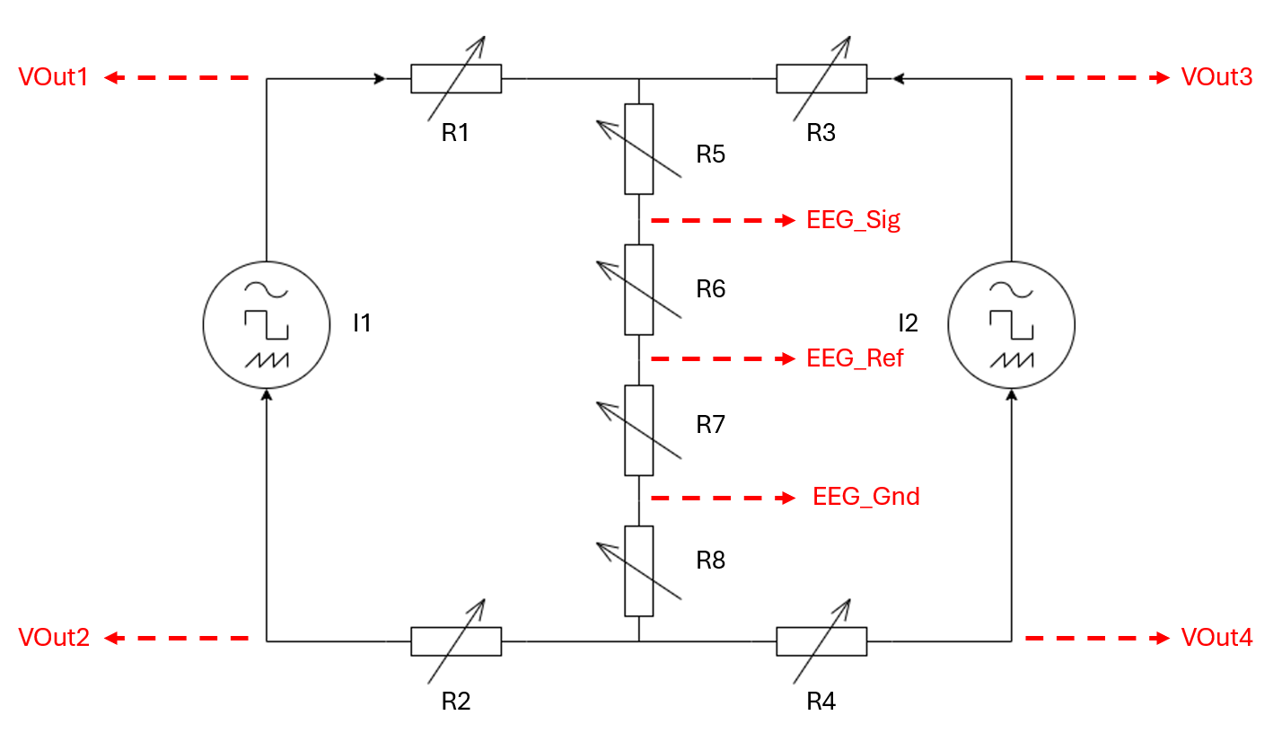
Example resistance values for the H-Bridge will be used throughout the documentation. For your own tests in preparation of your TI experiment, the exact resistor values to be used should be determined according to the electrode montage to be used in human experiments and observed impedances there. The guide for this process is here.
The documentation will make reference to the following variables:
| Label | Type | Unit | Detail |
|---|---|---|---|
| f | Frequency | Hz | The carrier frequency for Temporal Interference to be defined by the tester for their respective experiment objectives |
| I1 | Current | mA | The current amplitude for Temporal Interference channel 1, to be defined by the tester for their respective experiment objectives |
| I2 | Current | mA | The current amplitude for Temporal Interference channel 2, to be defined by the tester for their respective experiment objectives |
| Rsum | Resistance | Ohms | The sum of the impedance magnitudes for all impedances in R5, R6, R7 and R8. |